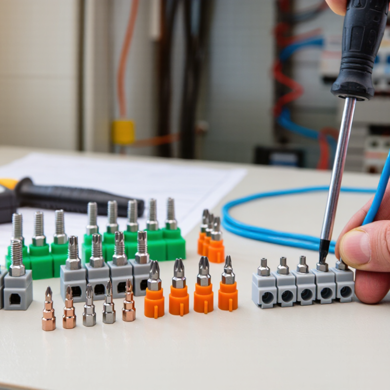
| Feed-Through Screw Terminal | Copper-alloy current bar, insulating thermoplastic housing, and a screw-clamp conductor connection. | Simple installation, broad conductor compatibility, and easy visual inspection. | Confirm the declared rated voltage, rated current, conductor size range, temperature rise, insulation properties, and tightening torque. | Request the applicable UL 1059 recognition or listing information, including the terminal-block category, wire range, voltage, current, and field-wiring conditions. | Obtain a current RoHS declaration for restricted substances and an EU Declaration of Conformity when CE marking is applicable to the complete equipment. | Control cabinets, switchgear, industrial machinery, power distribution, and equipment wiring. | Check markings on the terminal, test reports, torque specifications, conductor compatibility, and complete assembly ratings. |
| Spring-Clamp Terminal | Spring steel clamping element combined with a copper-alloy current path and flame-retardant insulating housing. | Resists loosening caused by vibration and generally reduces maintenance associated with retightening. | Verify tests for electrical performance, mechanical retention, conductor insertion, temperature rise, and compatibility with solid, stranded, or ferruled conductors. | Confirm whether the certified configuration permits the intended wire type, wire size, insulation temperature, and installation method. | RoHS status depends on the materials used. CE documentation should identify the applicable EU legislation for the finished product rather than treating CE as a standalone product certificate. | Vibration-prone machinery, factory automation, transportation equipment, and compact control panels. | Verify the required insertion tool, strip length, permissible conductor types, pull-out performance, and maintenance instructions. |
| Barrier Screw Terminal | Individual screw terminals separated by insulating barriers, often with a pressure plate or clamp system. | Provides clear circuit separation and can be suitable for higher-voltage or multi-circuit wiring layouts. | Confirm creepage distance, clearance, dielectric strength, rated voltage, rated current, and the permitted conductor termination method. | Check the UL 1059 file information for spacing, field-wiring suitability, wire range, and any restrictions on adjacent circuits. | Request the material declaration and RoHS evidence for housing, screws, barriers, plating, and any accessories. CE assessment remains dependent on the final equipment. | Power supplies, motor controls, industrial panels, HVAC equipment, and equipment requiring circuit segregation. | Compare the terminal spacing with the system voltage and pollution environment; verify torque and short-circuit requirements. |
| Protective-Earth Terminal | Metal current path with a green-and-yellow identification feature and a housing or mounting system designed for protective bonding. | Supports reliable protective-earth continuity and clear identification during installation and maintenance. | Confirm protective-circuit continuity, resistance, mechanical strength, corrosion protection, marking, and compatibility with the mounting rail or panel. | Verify the applicable grounding-terminal requirements, recognized configuration, conductor range, and permissible mounting method under the relevant UL file. | Check RoHS evidence for metal plating and insulation materials. CE compliance should be documented as part of the complete electrical equipment risk and conformity assessment. | Control cabinets, machine frames, distribution boards, and equipment requiring protective bonding. | Confirm green-and-yellow identification, earth continuity test results, mounting integrity, and compatibility with the protective conductor system. |
| Multi-Level Terminal | Two or more electrically separate terminal levels integrated into one insulating housing. | Saves panel space and increases wiring density while maintaining separate circuits. | Check level-to-level and terminal-to-terminal clearances, insulation system, rated current for each level, heat dissipation, and accessibility. | Verify that the UL 1059 certification covers the exact number of levels, conductor arrangement, wire range, voltage, and current combination. | Request a bill-of-materials-based RoHS declaration. CE documentation should cover the completed equipment and any relevant low-voltage or EMC requirements. | Compact control cabinets, automation systems, instrumentation, and high-density signal distribution. | Review derating data, test access, screwdriver clearance, jumper compatibility, labeling space, and thermal performance. |
| Disconnect or Fuse Terminal | Terminal block with a disconnect link, test point, fuse holder, or removable circuit-protection element. | Allows circuit isolation, testing, or localized overcurrent protection within the terminal assembly. | Verify the ratings of the complete configuration, including the disconnect mechanism, fuse type, touch protection, temperature rise, and short-circuit performance. | Confirm UL 1059 coverage for the exact fuse or disconnect arrangement, including fuse dimensions, voltage, current, wire range, and access conditions. | Check RoHS status of the terminal and replaceable components. CE conformity must also consider the protection function and the finished equipment design. | Measurement circuits, process control, safety-related isolation, instrumentation, and maintenance-friendly panels. | Verify fuse compatibility, replacement access, finger-safe protection, labeling, spare-part availability, and fault-current requirements. |



 © Copyright 2020 Tianjin Tanghaidongyang Valve Co., Ltd. All Rights Reserved.