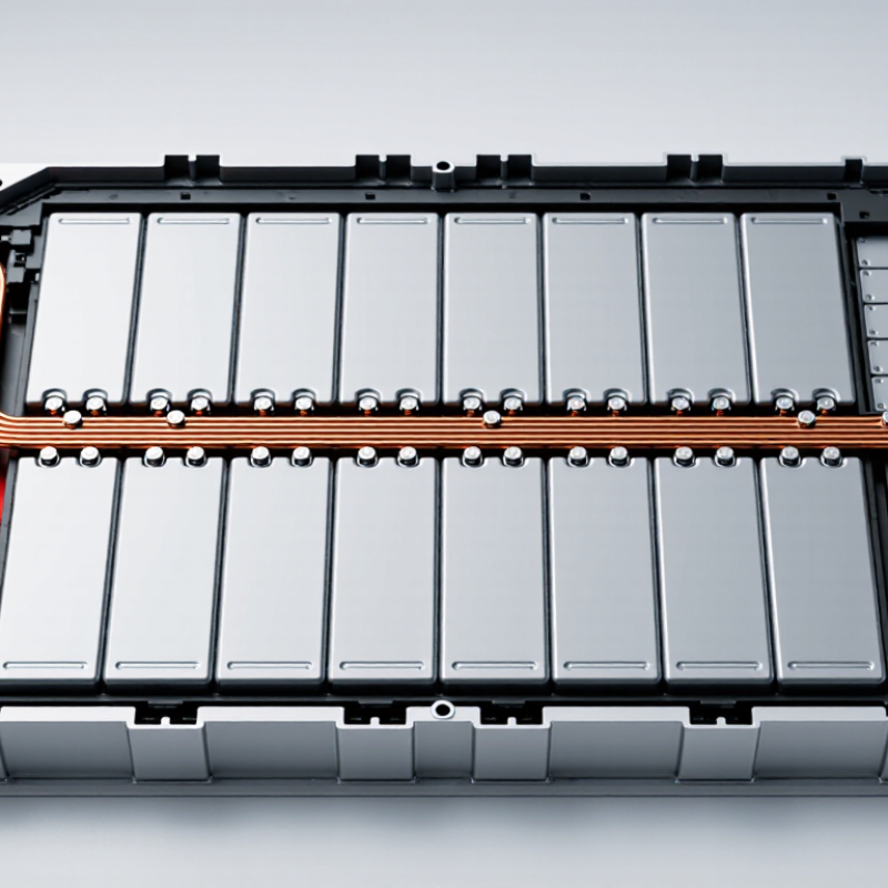
| Cell interconnection | Conductive busbars connect cell terminals in series, parallel, or series-parallel arrangements. | Creates electrical paths between cells and helps organize connections within a module or pack. |
| Conductor material | Copper and aluminum are commonly used. At about 20°C, their electrical conductivities are approximately 58 MS/m and 35 MS/m, respectively; actual values depend on material grade and condition. | Copper offers higher conductivity per cross-sectional area, while aluminum can reduce conductor mass. Material choice also affects joining, corrosion control, and cost. |
| Current-carrying capacity | No single current rating applies to all CCS busbars. Capacity is determined by conductor dimensions, joint resistance, cooling, allowable temperature rise, and pack layout. | Sizing for the application helps manage resistive heating and voltage drop under expected operating and fault conditions. |
| Temperature sensing | An integrated CCS may route sensor connections to cell or busbar areas. NTC thermistors are commonly used; a 10 kΩ nominal resistance at 25°C is one available specification, not a universal standard. | Sensor signals can be read by the battery-management system to support temperature monitoring and protective control strategies. |
| Signal routing | Flexible printed circuits or other insulated wiring can carry sensing and monitoring signals alongside the busbar assembly. | Combines cell interconnection and signal routing in a structured assembly, potentially reducing separate wiring and assembly steps. |
| Electrical insulation | Insulating carriers, films, or covers separate conductive paths and help protect against unintended contact. Required clearances and insulation ratings depend on pack voltage and applicable standards. | Supports electrical isolation and helps reduce the risk of short circuits when designed for the specific voltage, environment, and assembly. |
| Joining and contact resistance | Welding, bolting, or other qualified joining methods may be used, depending on cell terminals and conductor materials. Joint resistance and mechanical integrity require validation. | Reliable joints help limit localized heating and maintain electrical continuity through vibration and service conditions. |
| Thermal design | Temperature rise depends on current, conductor resistance, joint quality, heat transfer, and ambient conditions. Sensor placement should reflect the locations that need monitoring. | Integrated monitoring can help identify abnormal heating, but it does not replace thermal testing or appropriate protection design. |
| Mechanical integration | The assembly is designed around cell spacing, terminal positions, tolerances, expansion, vibration, and enclosure constraints. | A layout matched to the cell arrangement can simplify installation and reduce the chance of assembly interference. |
| Validation | Typical checks include dimensional inspection, continuity and resistance testing, insulation testing, thermal assessment, and mechanical evaluation. | Testing confirms that the complete assembly meets its specified electrical, thermal, and mechanical requirements. |



 © Copyright 2020 Tianjin Tanghaidongyang Valve Co., Ltd. All Rights Reserved.