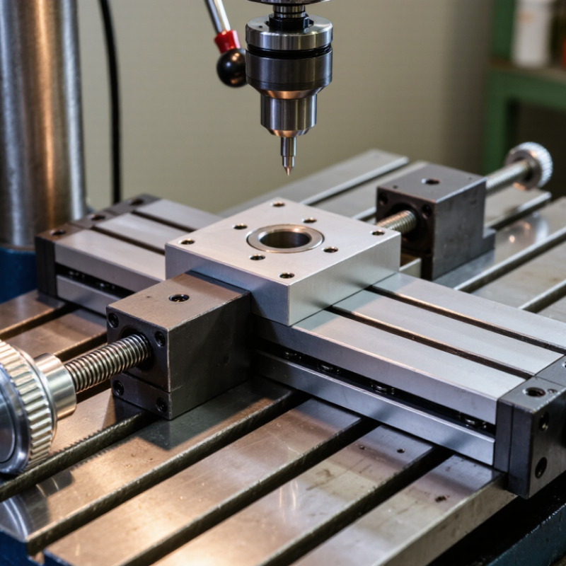
| Basic Definition | Mechanical Structure | A cross slide table is a compact positioning platform made of two sliding stages arranged at right angles. One stage provides movement along the X-axis, while the other provides movement along the Y-axis. | Manual positioning, inspection fixtures, laboratory setups, and small machine tools. | Confirm the required travel direction, available installation space, and compatibility with the mounting surface. |
| Operating Principle | Two-Axis Motion | Turning a handwheel or driving a screw moves one stage linearly. The second stage is mounted on top of the first and provides motion perpendicular to it, allowing controlled movement in two horizontal directions. | Component alignment, tool positioning, sample adjustment, and drilling or milling setup. | Select independent X and Y adjustment when precise two-axis alignment is needed. |
| Drive Mechanism | Lead Screw or Ball Screw | Lead screws are common in manual and general-purpose tables. Ball screws reduce friction and backlash and are more suitable for motorized systems requiring improved positioning performance. | Lead screws: manual machining and adjustment. Ball screws: CNC equipment, automation, and repeated positioning. | Consider required accuracy, repeatability, operating speed, load, maintenance, and budget. |
| Motion Control | Manual or Motorized | Manual tables use handwheels, knobs, or micrometer heads. Motorized versions use stepper motors, servo motors, or other actuators for programmable movement. | Manual inspection and setup; automated assembly, measurement, scanning, and machine-tool positioning. | Choose manual control for occasional adjustment and motorized control for automation, remote operation, or repeatable cycles. |
| Travel Range | X/Y Travel | Travel range is the maximum linear distance available on each axis. Compact tables may provide short travel for fine adjustment, while larger tables support broader positioning. | Short travel: optical alignment and inspection. Longer travel: machining, fixture positioning, and production equipment. | Specify the required travel on both axes and allow additional clearance for workholding and tool access. |
| Load Capacity | Static and Dynamic Load | Load capacity depends on bearing design, stage size, screw arrangement, load direction, and the distance between the load center and the table surface. | Supporting workpieces, inspection fixtures, cutting tools, sensors, cameras, and laboratory equipment. | Include the workpiece, fixture, tooling, and any dynamic forces. Use a safety margin rather than selecting at the exact rated limit. |
| Guidance System | Dovetail, Linear Bearing, or Profile Rail | Dovetail slides provide robust guided motion and are often adjustable. Rolling-element bearings and profile rails generally offer lower friction and smoother motion. | Dovetail slides: machining and rugged manual adjustment. Linear bearings or rails: precision positioning and automated motion. | Match the guide type to the required rigidity, smoothness, environmental conditions, speed, and maintenance schedule. |
| Accuracy | Positioning Accuracy and Repeatability | Accuracy describes how closely the table reaches a commanded position. Repeatability describes how consistently it returns to the same position. These values are affected by screw quality, guide clearance, stiffness, and assembly. | Dimensional inspection, optical alignment, precision assembly, and controlled tool positioning. | Define whether the process requires high absolute accuracy, high repeatability, or simply convenient manual adjustment. |
| Backlash | Clearance in the Drive System | Backlash is unwanted lost motion caused by clearance between mating screw and nut components. It can affect bidirectional positioning and contouring accuracy. | Critical in CNC machining, precision measurement, and automated positioning that changes direction frequently. | Consider an anti-backlash nut, preloaded screw, or ball screw when reversing direction must not create significant positioning error. |
| Rigidity | Resistance to Deflection | Rigidity is the table's ability to resist bending, twisting, and vibration under load. A rigid platform helps maintain alignment and cutting stability. | Milling, drilling, grinding, heavy fixtures, and applications involving cutting forces. | Evaluate table thickness, guide spacing, support area, material, and the distance from the load center to the slide. |
| Table Surface | Mounting Pattern and Work Area | The upper platform may include threaded holes, clearance holes, slots, or a plain surface for attaching fixtures and components. | Mounting vises, clamps, sensors, optical components, probes, and custom fixtures. | Verify hole spacing, thread type, usable surface area, and access for tools and fasteners. |
| Materials | Steel, Aluminum, or Cast Iron | Steel and cast iron generally provide higher stiffness and wear resistance. Aluminum reduces weight and is useful where portability or lower moving mass is important. | Steel or cast iron: machining and heavy-duty fixtures. Aluminum: laboratory, optical, and lightweight automation systems. | Balance mass, stiffness, corrosion resistance, thermal behavior, and expected wear. |
| Environment | Dust, Chips, Moisture, and Temperature | Contaminants can increase friction and wear, while moisture may cause corrosion. Temperature changes can affect dimensions and positioning accuracy. | Clean laboratories, machine shops, production lines, outdoor equipment, and process environments. | Consider covers, seals, corrosion-resistant materials, lubrication requirements, cleaning access, and operating temperature. |
| Common Applications | Machining and Fabrication | Cross slide tables are used to position workpieces or tools during drilling, milling, engraving, grinding, and other operations requiring controlled planar movement. | Drill presses, small mills, engraving machines, fixture systems, and custom fabrication equipment. | Prioritize rigidity, load capacity, travel, backlash control, and compatibility with cutting forces. |
| Common Applications | Inspection and Measurement | The table provides fine adjustment for positioning a part, probe, camera, sensor, or measuring device relative to a reference point. | Dimensional inspection, visual inspection, sensor alignment, and laboratory measurement. | Prioritize smooth motion, low backlash, repeatability, fine adjustment resolution, and stable mounting. |
| Common Applications | Optical and Laboratory Equipment | Compact cross slide tables allow precise horizontal adjustment of samples, lenses, detectors, stages, and experimental fixtures. | Optical alignment, microscopy accessories, research equipment, and test benches. | Check vibration resistance, adjustment sensitivity, surface flatness, cleanliness, and compatibility with the laboratory setup. |
| Common Applications | Automation and Assembly | Motorized cross slide tables can move components through programmed X/Y positions for assembly, dispensing, testing, marking, or inspection. | Pick-and-place systems, dispensing equipment, camera inspection, testing stations, and light-duty automation. | Evaluate cycle rate, acceleration, motor compatibility, controller interface, cable routing, and repeatability. |
| Maintenance | Lubrication and Adjustment | Proper lubrication reduces wear and friction. Periodic inspection may be needed to check fasteners, guide clearance, screw condition, and surface contamination. | All manual and motorized cross slide table installations. | Select a design with accessible lubrication points and adjustment features appropriate for the operating environment. |



 © Copyright 2020 Tianjin Tanghaidongyang Valve Co., Ltd. All Rights Reserved.