Certificates

Certificates

What Are Globe Valves and How Do They Work?

Globe valves are engineered for controlled fluid movement, not merely open-or-closed service. Their rounded body houses a movable disc, stem, and stationary seat. When the handwheel turns, the stem moves the disc toward or away from the seat. This changes the flow passage with measurable precision. Small adjustments can regulate steam, water, oil, and many process fluids.

One detail matters. Globe valves create more pressure loss than gate valves because fluid changes direction inside the body. That resistance can improve throttling, but it may increase pumping costs. The U.S. Department of Energy identifies pumping systems as major industrial energy users, making valve selection relevant to operating efficiency. The report also stresses proper sizing, maintenance, and system optimization. A valve that is too large may operate near its seat, while an undersized valve can cause excessive velocity and noise.

Industry standards provide the technical foundation. ASME B16.34 addresses pressure-temperature ratings, materials, and testing requirements for many industrial valves. API 623 focuses specifically on steel globe valves used in petroleum and natural gas services. Grand View Research reported that the global industrial valves market was valued at more than USD 78 billion in 2023, reflecting demand across energy, water, chemical, and manufacturing facilities. Market estimates vary by definition and region, so they should not replace engineering judgment. In practice, correct globe valve performance depends on pressure, temperature, fluid chemistry, flow rate, and maintenance quality. This guide explains their construction, operating principle, applications, limitations, and selection considerations. The simple design deserves closer attention.

What Are Globe Valves and How Do They Work?

Globe Valve Definition and Core Components

Globe Valve Overview

A globe valve is a mechanical device used to regulate or stop fluid flow. Its defining feature is a movable disc that travels toward or away from a fixed seating surface. This movement changes the flow passage gradually. Unlike a simple on-off valve, a globe valve can provide accurate throttling. Its main body contains the inlet and outlet ports, while the bonnet protects the internal mechanism. The stem connects the handwheel or actuator to the disc.

Core Components and Operation

The core components include the body, bonnet, stem, disc, seat, and packing. The seat forms the sealing surface inside the body. When the stem moves downward, the disc presses against the seat and restricts flow. Lifting the stem creates more space for fluid to pass. Packing surrounds the stem and helps prevent leakage to the outside. Small design details matter. Poor alignment or damaged packing can reduce performance quickly. Flow direction also affects pressure loss and operating effort.

Tips: Check the valve material, pressure rating, temperature range, and fluid compatibility before installation. Tighten connections evenly, but do not force them. A globe valve usually creates more pressure drop than a straight-through valve. That trade-off is sometimes overlooked. Correct sizing is not purely a calculation; operating conditions may change. Regular inspection should include stem movement, external leakage, unusual noise, and signs of corrosion.

How Fluid Flows Through a Globe Valve

What Are Globe Valves and How Do They Work?

How Fluid Flows Through a Globe Valve

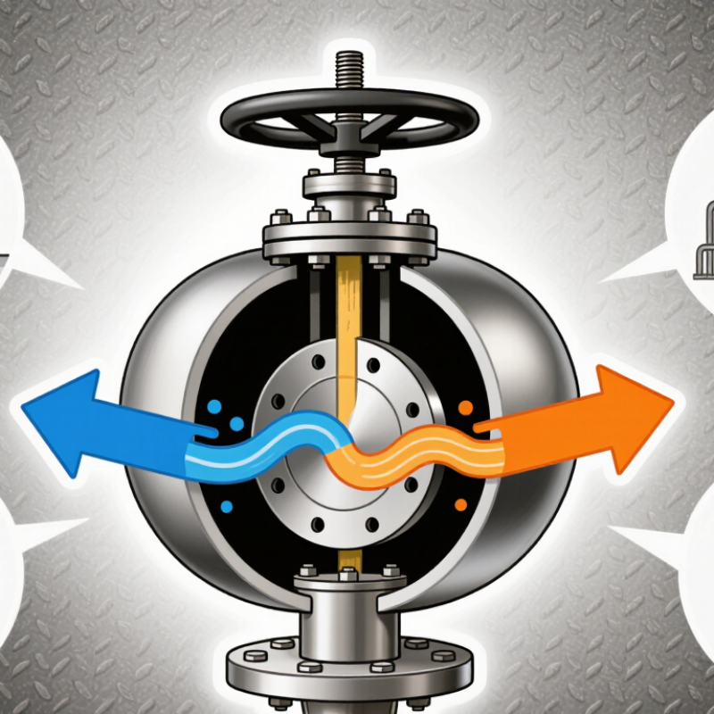
A globe valve controls fluid by moving a plug toward or away from a fixed seat. The stem transfers movement from the handwheel or actuator. When the plug lifts, fluid enters the valve body and changes direction around an internal baffle. It then passes through the opening beneath the plug. This curved path creates resistance, which helps regulate flow accurately. It also produces more pressure loss than a straight-through valve.

Small stem movements can create noticeable changes in flow. That makes globe valves useful for steam, water, air, and process fluids. The exact response depends on the plug and seat design. Some trims provide nearly linear control, while others suit equal-percentage regulation. Flow direction also matters. In many designs, fluid should enter below the plug. This arrangement can reduce closing force, but the manufacturer’s flow arrow remains essential.

A practical inspection should look for seat erosion, plug damage, and unusual vibration. Wire-drawing may appear as fine grooves on metal surfaces. Cavitation can sound like gravel inside the body. It may occur when pressure drops sharply across the valve. A simple diagram can mislead because real piping includes pressure changes, heat, and installation limits. The valve must match the fluid, temperature, pressure, and required control range. Not every globe valve performs well as a frequent isolation valve. Its strength is controlled throttling.

Step-by-Step Operating Principle of a Globe Valve

What Are Globe Valves and How Do They Work?

A globe valve controls fluid flow with a movable disc, a stationary seat, and a stem. Its rounded body creates the familiar globe-like shape. The valve may handle water, steam, air, or process liquids when its materials match the service conditions.

Step-by-Step Operating Principle of a Globe Valve

When an operator turns the handwheel, the stem moves the disc in a straight line. The disc does not rotate against the seat. It rises to open the passage and lowers to restrict it. Small movements can produce careful flow adjustment.

With the disc partly closed, fluid passes through a narrow gap. The flow changes direction inside the body, creating pressure loss but improving control. When the disc contacts the seat, the valve stops the flow. The sealing surfaces must remain clean and undamaged.

Inspect the stem, packing, and seat regularly. A stiff handwheel may indicate corrosion, excessive pressure, or misalignment. Do not force it. That can damage the stem or deform the seat.

Installation details matter. Follow the flow arrow and the manufacturer’s pressure-temperature rating. In practical systems, the ideal direction may vary with pressure, temperature, and service fluid. That is an area requiring careful review, not guesswork. Even a correctly selected globe valve can leak if debris remains on the seating surface.

Main Globe Valve Designs and Their Differences

Globe valves regulate flow by moving a disc against a stationary seat. The disc travels vertically, so operators can adjust flow accurately. They also provide dependable shutoff in many process systems. However, their curved internal passage creates more pressure loss than a gate valve.

The standard Z-body design is common in pipelines and general service. Its seat and stem arrangement is simple, accessible, and relatively easy to maintain.

The Y-body design places the stem at an angle, creating a straighter flow path. It usually reduces pressure loss, especially in high-pressure applications.

An angle globe valve turns the flow direction by 90 degrees. This design can replace a separate elbow, saving space and reducing connection points. Still, its performance depends heavily on correct sizing. No pattern wins every service.

Tips: Check the pressure drop, temperature, fluid composition, and expected throttling range before selection. Field inspections should also examine seat wear, stem alignment, and signs of cavitation, such as a sharp rattling sound or pitted metal. A smaller valve is not automatically more efficient. Oversizing can make control unstable, while undersizing may cause excessive velocity. The design boundaries are not always perfect. A reliable choice balances layout, maintenance access, and real operating conditions.

Common Applications, Benefits, and Limitations

A globe valve controls flow through a plug that moves toward or away from a shaped seat. The handwheel or actuator moves the stem vertically. Flow changes as the opening narrows. This design gives operators accurate throttling, especially when pressure or temperature must remain stable. The body usually redirects flow around the plug, creating more resistance than a gate valve.

Common applications include steam lines, cooling-water systems, chemical processing, and boiler feed services. Operators value globe valves because they provide repeatable adjustment and reliable shutoff. Proper sizing matters. An oversized valve may operate almost closed, making control unstable. The U.S. Department of Energy reports that pumping systems can consume 25% to 50% of industrial electricity. Unnecessary valve pressure loss can therefore increase operating costs. Small losses become expensive.

The limitation is clear. Globe valves usually create higher pressure drop than low-resistance isolation valves. Their seats and plugs can also suffer erosion under high-velocity, abrasive flow. The IEA’s Energy Efficiency 2023 report states that industry used about 37% of global final energy in 2022. Efficiency deserves attention. In field work, I would not blame every energy loss on the valve. Poor pipe sizing, dirty strainers, and inaccurate instruments may contribute more. ASME B16.34 and IEC 60534 provide useful design and control guidance, but real service conditions still require engineering judgment. Perfect control is rarely achieved.