| Material Definition | Confirm whether “carbide” refers to a carbide tip, carbide wear section, or a carbide-containing electrode body. | Carbide is not the usual bulk material for grounding electrodes. Common electrode constructions include copper-clad steel, galvanized steel, stainless steel, and solid copper. | Request a material declaration, cross-sectional drawing, and technical datasheet before purchase. | Marketing terminology can conceal differences in electrical conductivity, corrosion behavior, mechanical strength, and code acceptance. |
| Electrical Conductivity | Review the conductive path from the grounding conductor to the surrounding soil, including joints and connectors. | For a grounding electrode, soil contact area and installation depth usually have more influence on grounding resistance than the small difference between common conductive metals. | Use a continuous, corrosion-resistant conductive body and a listed connector compatible with the electrode material. | A mechanically strong rod is not sufficient if the connection becomes electrically discontinuous or highly resistive. |
| Diameter and Length | Compare actual outside diameter, length, tip geometry, couplers, and driving accessories. | Typical commercial rods are approximately 14–20 mm in diameter and 2.4–3.0 m long, but required dimensions depend on local electrical rules, soil, and available installation depth. | Choose the longest practical listed electrode permitted by the local design and installation conditions. | Greater length can provide access to lower-resistivity soil and may be more effective than simply increasing diameter. |
| Corrosion Protection | Check coating type, minimum coating thickness, adhesion, exposed steel at cut ends, and compatibility with soil chemistry. | Copper-clad and stainless-steel rods generally provide better long-term corrosion resistance than unprotected carbon steel. Galvanized steel performance depends strongly on soil chemistry and coating condition. | Use a continuously bonded copper cladding or corrosion-resistant alloy with documented coating thickness and quality testing. | Corrosion can reduce cross-section, weaken the rod, increase resistance, and make future testing or maintenance difficult. |
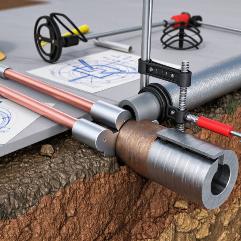
| Mechanical Driving Strength | Assess hardness of the driving tip, rod straightness, tensile strength, thread quality, and resistance to mushrooming. | A hardened or carbide-tipped driving point can help in compact or gravelly soil, but a tip does not automatically improve the rod’s electrical performance or corrosion life. | Use a compatible driving head and coupler; do not strike the exposed threaded end directly with a hammer. | Damage during installation can crack coatings, deform couplers, or create hidden electrical and corrosion weaknesses. |
| Applicable Standards | Verify the exact edition and scope of the standards required by the project jurisdiction. | Common references include UL 467 for grounding and bonding equipment, IEC 62561-2 for earth electrodes, IEEE 80 for substation grounding design, and NEC Articles 250.52 and 250.53 where the NEC applies. | Select a product with a current third-party listing or test report covering the complete electrode and connector system. | Compliance depends on the complete installed system, not only on the rod’s material name or laboratory conductivity. |
| Connector Compatibility | Check connector listing, conductor size range, material compatibility, installation torque, and protection against galvanic corrosion. | Directly joining dissimilar metals can accelerate galvanic corrosion, especially in wet or saline soil. Exothermic welding and listed mechanical connectors are common connection methods. | Use a listed connector specifically approved for the selected rod material and grounding conductor. | The connection is often the most vulnerable point in the grounding system. |
| Grounding Resistance Target | Define the design objective instead of selecting a rod solely by a resistance number. | A commonly used design goal is 25 ohms or less for a single electrode in some NEC applications, while sensitive facilities may specify lower values. Local rules and engineering requirements control. | Measure the completed system using an appropriate fall-of-potential or approved clamp-based method where applicable. | Rod material alone cannot guarantee a specific resistance because soil resistivity, moisture, depth, spacing, and electrode quantity are decisive. |
| Indicative Purchase Cost | Compare rod, tip, coupler, connector, freight, installation tools, labor, testing, and replacement cost. | Standard copper-clad or galvanized rods are generally lower-cost options. Specialized carbide-tipped or custom corrosion-resistant designs usually carry a premium, while installation and access costs can exceed the rod price. | Compare total installed cost rather than unit price; obtain quotations based on identical diameter, length, coating, certification, and accessories. | A low-cost rod can become expensive if it requires frequent replacement, special tooling, or corrective grounding work. |
| Expected Service Life | Evaluate soil pH, chloride and sulfate content, moisture, stray current, coating thickness, and mechanical damage. | Service life can range from several years in aggressive soil to several decades in favorable soil. A universal service-life guarantee is not technically reliable without site-specific corrosion data. | Use soil testing and a corrosion assessment for critical or high-value installations. | Environmental conditions can change the service life more significantly than the rod’s nominal material category. |
| Quality-Control Evidence | Request dimensional inspection records, coating-thickness results, adhesion tests, conductivity or continuity checks, and batch traceability. | Reliable documentation should identify the production batch and test method rather than provide only a general certificate. | Prefer suppliers able to provide lot-specific reports and samples for independent verification. | Traceable evidence makes it easier to compare suppliers and resolve failures during inspection or commissioning. |
| Installation Environment | Consider rocky soil, urban utilities, buried pipelines, frozen ground, groundwater, and access for driving equipment. | Driving may be unsuitable in rock or congested areas. Alternative electrodes, drilled installations, horizontal conductors, or additional bonded electrodes may be required. | Complete a site survey before finalizing rod length, tip design, and installation method. | The best rod specification cannot compensate for an installation method that is unsafe or unsuitable for the site. |
| Maintenance and Inspection | Plan continuity checks, resistance testing, visual inspection of accessible connections, and records of soil or system changes. | Buried rods are difficult to inspect directly; accessible connections and test points should therefore be designed for periodic verification. | Include test points, labeled conductors, and a documented inspection schedule in the grounding design. | Routine verification identifies loose connections, corrosion, accidental disconnection, and changes in grounding performance. |



 © Copyright 2020 Tianjin Tanghaidongyang Valve Co., Ltd. All Rights Reserved.