Certificates

Certificates

How to Choose the Right CCS Busbar?

Choosing the right CCS Busbar starts with understanding the battery system it must serve. A busbar connects cells and modules, so its design can affect current flow, heat, packaging, and assembly. The best option is not simply the thickest or most conductive one. It must suit the operating current, available space, connection points, and the conditions inside the battery pack.

Begin by checking the required current and the busbar’s material, thickness, and cross-section. These factors influence electrical resistance and heat generation. Then consider the full assembly: terminal positions, bend locations, insulation, sensor connections, and clearance from nearby parts. A drawing may look correct while leaving too little room for tools or protective covers. Small details matter. Vibration and thermal cycling also deserve attention, particularly where joints and supports meet.

There is no universal best choice. That deserves attention. A design that works in one battery layout may create installation or thermal issues in another. Ask suppliers for relevant drawings, material specifications, test information, and manufacturing tolerances. Where possible, review fit and connection quality with a physical sample before committing to production. Engineers should validate the design against the system’s actual electrical and environmental requirements; general guidance cannot replace that review. Even a careful selection process may reveal assumptions that need revisiting. That is useful, not a failure. A well-chosen CCS Busbar is one that fits the application, can be assembled consistently, and performs reliably under its intended conditions.

How to Choose the Right CCS Busbar?

Identify the CCS Busbar’s Function in Your Application

How to Choose the Right CCS Busbar?
Identify the CCS Busbar’s Function in Your Application

A CCS busbar, or cell contacting system busbar, links battery cells and may carry current, support voltage sensing, or both. Start with its job. Map the electrical path from cell terminals to the module output, then note where measurement connections and insulation are needed. The International Energy Agency’s Global EV Outlook 2024 reports nearly 14 million electric car sales in 2023, about 18% of global car sales. This growth makes dependable battery connections increasingly important, but the right design still depends on the specific pack.

Define current, operating voltage, temperature range, available space, and expected vibration before comparing designs. Then check conductor material, thickness, terminal layout, insulation, and sensing-tab placement against those requirements. A busbar that carries current well may still complicate assembly if its tabs obstruct nearby components. Ask for resistance, temperature-rise, and mechanical test results under conditions close to your application. A tidy drawing can hide a fit problem. I’ve seen small alignment differences matter more than expected.

Tips: Mark the current path and sensing points on a module drawing. Confirm clearances around cell terminals and fasteners. Compare test data, not just nominal ratings. Record assumptions; they may need revisiting after prototype testing.

How to Choose the Right CCS Busbar? — Identify the CCS Busbar’s Function in Your Application

Application or Pack Area Primary CCS Busbar Function What to Check When Selecting Useful Design or Inspection Points
Cell-to-cell connections within a module Connects cell terminals in the required series or parallel arrangement to form the module’s electrical path. Cell-terminal layout, connection sequence, required current, available space, and the cell manufacturer’s terminal limits. Confirm polarity and connection geometry. Check that joints are compatible with the specified joining process and that the busbar does not place undue mechanical load on terminals.
Cell-voltage monitoring Provides connection points for voltage-sensing leads or integrated sensing circuits so the battery management system can monitor cell or group voltages. Number and location of measurement points, sensing-circuit routing, insulation, and separation between measurement and power paths. Verify that sensing connections correspond to the electrical schematic. Protect small signal conductors from abrasion, pinching, and unintended contact with power conductors.
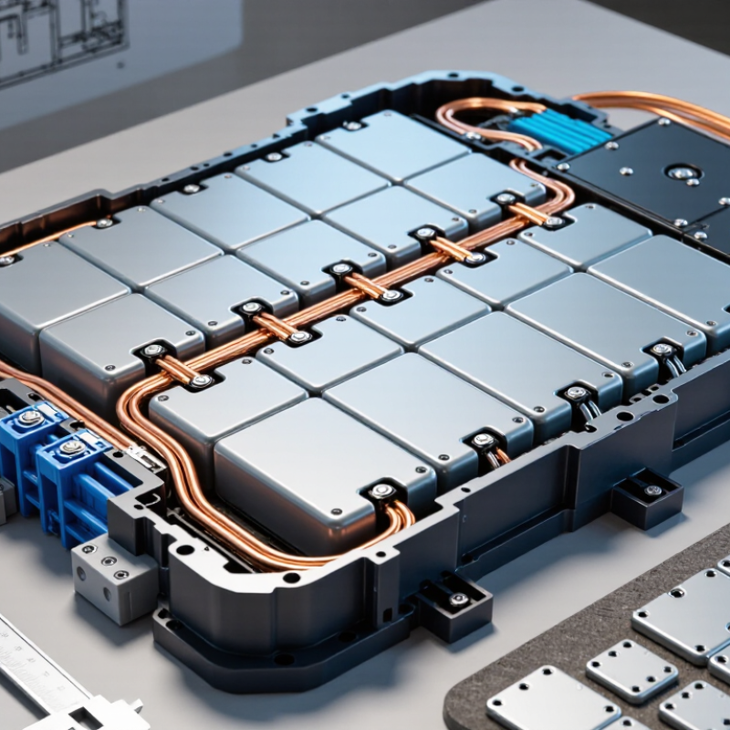
Module-level cell contacting system (CCS) Combines conductive busbars with an insulating carrier and, where specified, voltage-sensing components into an organized cell-interconnection assembly. Cell pitch, carrier fit, terminal access, creepage and clearance requirements, material compatibility, and assembly sequence. Check alignment against the actual cell and module tolerances. Ensure the carrier retains conductors securely without obstructing cooling features or service access.
Module-to-module or module-to-pack connection Carries current between modules or connects a module to a pack-level electrical node. Pack voltage and current requirements, fault-current conditions, connection interfaces, vibration exposure, and installation clearances. Assess conductor heating and voltage drop under the intended operating conditions. Use the pack design’s specified insulation, protection, and joining requirements.
High-vibration or moving installation Maintains electrical continuity while the battery assembly experiences vibration and mechanical movement. Support points, conductor geometry, joint design, thermal expansion, and the vibration environment defined for the product. Look for adequate support and strain relief. Inspect joints and nearby insulation for signs of loosening, fatigue, fretting, or contact with adjacent parts.
Compact or space-constrained battery pack Routes electrical connections and sensing features within the available module envelope. Busbar profile, bend or routing space, terminal access, insulation thickness, and clearance from the enclosure and other conductors. Check the complete assembly, not just the bare conductor, for fit. Allow for manufacturing tolerances and avoid sharp edges that could damage insulation.
Thermally demanding operating conditions Conducts current while limiting unacceptable temperature rise in the busbar, joints, and surrounding components. Continuous and peak current profile, conductor material and cross-section, joint resistance, cooling conditions, and allowable temperatures of adjacent materials. Validate temperature rise in representative operating conditions. Do not select a busbar from a nominal current value alone; the complete assembly and environment affect performance.
Service, inspection, or replacement access Provides defined electrical connections that can be inspected or serviced according to the pack’s maintenance procedure. Fastener or joining method, accessibility, isolation procedure, replaceability, and protection against accidental contact. Follow the battery system’s approved isolation and service instructions. Confirm that inspection points are accessible without damaging the carrier, sensing circuit, or insulation.

Selection note: A CCS busbar is part of a complete battery interconnection system. Final selection should be verified against the cell and pack specifications, electrical and thermal requirements, insulation coordination, mechanical environment, and applicable safety standards.

Define Electrical, Thermal, and Mechanical Requirements

Choosing the right CCS busbar starts with its real operating duty, not just the charger’s rated output. Define nominal voltage, continuous current, short-duration peak current, and fault-current exposure. IEA’s Global EV Outlook 2024 reports that public charging points grew by 40% in 2023, while fast chargers grew by 55%. Higher-power charging makes current capacity and heat removal especially important.

For electrical sizing, check conductor material, cross-section, joint resistance, and acceptable voltage drop. Then assess temperature rise under the worst credible ambient conditions and charging cycle. A busbar that passes a brief peak may still overheat during repeated sessions.

Mechanically, confirm support spacing, enclosure clearance, connector forces, vibration, and thermal expansion. A clean CAD fit can still miss a tight bend or a service-access problem.

Tips: Ask for temperature-rise and short-circuit test evidence for the intended configuration. Compare measurements at the joints, not only along the busbar. Keep a margin, but avoid oversizing without checking weight, fit, and cost. I would also revisit assumptions after prototype testing; calculated temperatures do not always match a crowded enclosure.

Compare Materials, Shapes, and Connection Options

Choosing a CCS busbar starts with confirming what the specification means by CCS. The abbreviation can refer to different material constructions, so check the layer structure, conductivity, and temperature limits on the drawing or datasheet. A copper surface can support reliable electrical contact, while the core affects weight, strength, and heat flow. Do not compare materials by appearance alone. A small cut edge can reveal more than a polished face.

Shape matters just as much. Flat strips fit tight battery assemblies, while formed bends can route around terminals and reduce extra joints. Wider sections may lower resistance, but they also need more installation space. Check current, permitted temperature rise, vibration, and available clearance together. A neat-looking bend is not automatically a good one.

Connection options include bolted joints, welded tabs, and purpose-designed terminals. Bolted connections are serviceable, but contact surfaces must stay clean and fasteners need controlled torque. Welding can save space, yet heat may damage nearby insulation or alter the busbar’s coating. Prototype the actual joint, then inspect it after thermal and vibration testing. I would not rely on a catalogue rating alone; real assemblies can behave differently.

How to Choose the Right CCS Busbar?

Compare materials, shapes, and connection options for battery-pack current paths.

Material data: Typical values near 20°C; conductivity varies with alloy and temper. Copper is more conductive by volume, while aluminum is much lighter. Shape: Flat busbars suit compact, simple layouts; formed profiles can route around pack components. Connections: Welding creates a permanent, low-profile joint; bolted joints are easier to service but need suitable contact design and controlled tightening. Confirm current, temperature rise, vibration, and joining requirements for the specific pack.

Verify Safety Standards and System Compatibility

A CCS busbar must meet the safety requirements of the complete charging system, not just its own datasheet. Identify the applicable standards and current editions for the equipment’s market. Depending on the design, these may include requirements for charging equipment, connectors, insulation, and electrical clearances. Confirm the exact scope with a qualified engineer or testing laboratory; a familiar standard name alone is not proof of compliance.

Check the busbar’s rated voltage and current against the charger’s operating range. Then review temperature rise, insulation strength, creepage and clearance distances, and short-circuit withstand capability. These figures need to match real installation conditions, including enclosure temperature and cooling airflow. A busbar that passes a bench check may behave differently inside a crowded cabinet. That detail is easy to overlook.

Compatibility also depends on physical interfaces. Compare terminal dimensions, hole patterns, conductor material, plating, and approved joining methods with the system drawings. Verify clearances around nearby components and confirm that the assembly can be installed and serviced safely. Ask for traceable test reports and production inspection records, not only a product sheet. I would still question any design that relies on tight tolerances without a clear installation check. Small mismatches can become hot spots. Test the assembled system under representative load before approval.

Evaluate Suppliers and Validate the Final Selection

A CCS busbar supplier should be judged on process evidence, not a polished sample alone. The IEA’s Global EV Outlook 2024 reports that electric-car battery demand exceeded 750 GWh in 2023, about 40% above 2022. That scale makes repeatable quality essential. Ask for documented controls covering conductor material, plating, insulation, welding, and dimensional inspection. Request traceability from incoming material to finished assemblies, plus capability data for critical tolerances. A certificate helps, but it does not prove that a supplier can hold your design’s requirements.

Validate parts in the intended battery stack. Check electrical resistance and temperature rise at your specified current, then assess insulation, vibration, and mechanical retention under relevant conditions. Review test methods, sample sizes, and acceptance limits before approval; results without those details are hard to compare. A neat prototype may still conceal variation between production lots. That is easy to miss. I would also compare samples from more than one production run, even when schedules feel tight.

Tips: Send suppliers the same drawing revision and test conditions. Keep one approved reference sample, record deviations, and ask how process changes are controlled. Test the real stack. A checklist can feel tedious, and it may need revision after early builds. That is useful feedback, not a failure.