| Process Measurement | One active or passive 4–20 mA transmitter loop | Two electrically isolated 4–20 mA outputs | Pressure, level, flow, and temperature transmitters | Confirm whether the transmitter requires loop power from the splitter. Check the total load resistance of the input loop and both output circuits. | Apply known input values near 4 mA, 12 mA, and 20 mA, then compare both outputs with calibrated meters. |
| Control and Monitoring | 4–20 mA process variable from a field instrument | One output to a PLC or DCS and one output to a local indicator | Control valves, supervisory displays, and control-room monitoring | Use isolated outputs when the PLC, DCS, or indicator has a different ground reference. Verify input resistance and voltage compliance for each receiving device. | Test the signal at the splitter terminals and at the receiving equipment while all devices are connected. |
| Hazardous-Area Interface | 4–20 mA signal from a field transmitter | Galvanically isolated output circuits, subject to system certification | Petrochemical, chemical, and energy processing areas | Select equipment with the required hazardous-area, intrinsic-safety, or galvanic-isolation approvals. Follow the installation method and wiring limitations specified for the site. | Check approval markings, entity parameters where applicable, grounding arrangements, and loop continuity before energizing. |
| Remote Data Acquisition | 4–20 mA signal from a sensor or transmitter | One output to a remote I/O module and one output to a data logger | Water treatment, environmental monitoring, and utility systems | Consider cable length, voltage drop, electromagnetic interference, and surge exposure. Use shielded twisted-pair cable where appropriate. | Measure the current at both output terminals and confirm stable readings during normal cable routing and operating conditions. |
| Signal Distribution | Standard 4–20 mA analog signal | Two or more proportional outputs, depending on the device design | Distribution of one measurement to separate control, alarm, and recording systems | Check whether each output is active or passive. Do not connect an active output to an input that supplies loop power unless the circuit design permits it. | Verify output polarity, scaling, zero point, span, and the response of every connected input. |
| Temperature Monitoring | 4–20 mA output from a temperature transmitter | Isolated 4–20 mA outputs for controller and display | RTD or thermocouple transmitter applications | Install the splitter away from high-temperature surfaces and high-current switching equipment. Confirm that the transmitter range matches the receiving-system range. | Use a calibrated temperature simulator or current source to check linearity at multiple points. |
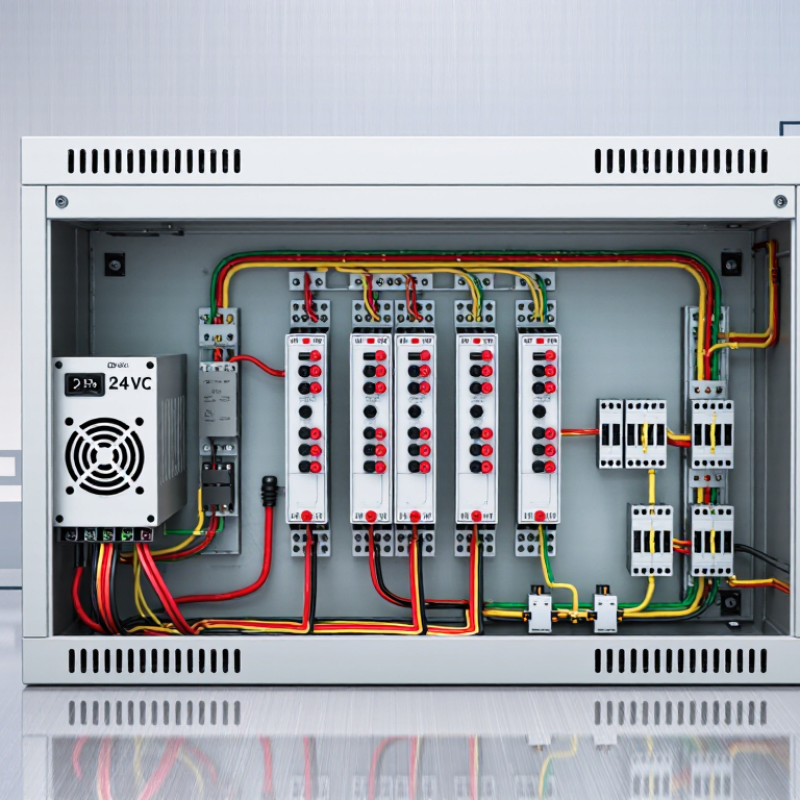
| Panel Installation | Single or dual 4–20 mA loop connection | DIN-rail mounted signal distribution module | Control cabinets, marshalling panels, and instrument panels | Provide adequate clearance for wiring and ventilation. Secure the device to the correct DIN rail and label all terminals before commissioning. | Inspect terminal tightness, conductor identification, polarity, and continuity against the approved wiring diagram. |
| Power Supply Arrangement | 4–20 mA input requiring loop excitation | Outputs powered by an external DC supply or by the receiving loop | Two-wire transmitters and distributed instrumentation systems | Confirm the required supply voltage, current capacity, polarity, and minimum operating voltage. Account for voltage drops across the transmitter, splitter, cable, and receiver. | Measure the supply voltage under load and verify that the loop remains within the specified compliance range. |
| Grounding and Isolation | 4–20 mA signal with possible ground-potential differences | Galvanically isolated input and output channels | Systems with separate power supplies, long cable runs, or multiple control panels | Use isolation to reduce ground loops and unwanted circulating currents. Ground cable shields according to the site grounding standard, commonly at one designated end. | Check resistance to protective earth where required and observe the signal for noise with all circuits operating. |
| Calibration and Commissioning | Simulated 4–20 mA input | Proportional duplicated outputs | Factory acceptance tests, loop checks, and maintenance activities | Use a calibrated loop source or process calibrator. Record zero, span, output deviation, and alarm behavior before placing the loop into service. | Document readings at 4 mA, 8 mA, 12 mA, 16 mA, and 20 mA, or at the points required by the project specification. |
| Environmental Protection | 4–20 mA signal in industrial conditions | Enclosed or open-panel signal splitter | Outdoor cabinets, humid areas, dusty plants, and vibration-prone equipment rooms | Confirm the enclosure rating, operating temperature, humidity limits, vibration suitability, and corrosion protection. Keep wiring entrances sealed where necessary. | Inspect the enclosure, cable glands, terminal condition, and operating temperature during a representative running period. |



 © Copyright 2020 Tianjin Tanghaidongyang Valve Co., Ltd. All Rights Reserved.