| Fire detection | May use linear heat-detection tubing or cable, discrete heat detectors, or other system-specific sensors. | Detects heat or a specified temperature condition in a protected area and initiates an alarm or suppression sequence, depending on the system design. | Detection lines are commonly routed through high-risk areas such as engine compartments. Placement must account for heat sources, vibration, and the protected-zone layout. |
| Control or actuation unit | Mechanical, pneumatic, electrical, or combined actuation, depending on system design. | Receives or responds to a detection event and releases the agent. Some systems also provide a driver warning or interface with vehicle controls. | Electrical systems may require suitable power and protected wiring. The release method and any vehicle shutdown functions should be specified for the vehicle and hazard. |
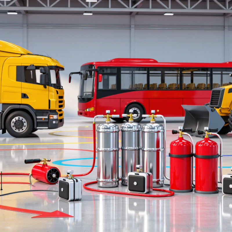
| Agent container | A pressure-rated cylinder or container holding the specified extinguishing agent and, where applicable, a propellant. | When actuated, the container releases agent into the connected distribution network. | Container location should allow secure mounting, inspection, and servicing while remaining protected from impact and excessive heat. |
| Extinguishing agent | Depending on the hazard and engineered system, options may include dry chemical, foam, water-based agents, or clean agents. | Agents control fire through mechanisms such as interrupting combustion, cooling, or suppressing flames. Their suitability depends on the materials and fire risks involved. | Agent selection should consider fuel, lubricants, electrical equipment, enclosed-space exposure, cleanup needs, and the system’s approved design. No single agent is suitable for every vehicle hazard. |
| Distribution piping or tubing | Fixed pipework or tubing connects the agent container to one or more discharge points. | Conveys the released agent to the intended protected zones. | Routing should be secured against vibration, abrasion, heat, and obstruction. Layout and component compatibility must follow the system design. |
| Discharge nozzles | Open or capped nozzles selected and positioned for the protected compartment and agent. | Direct and distribute the agent across designated hazard areas when the system discharges. | Nozzle location and orientation affect coverage. Nozzles should remain unobstructed and should not be treated as interchangeable between agents or system designs. |
| Manual release and warning devices | May include a manual release control, audible or visual alarms, and system-status indicators. | Manual controls can provide a means to initiate discharge; alarms can alert the operator to a detected fire or system activation. | Controls should be accessible to the operator but protected against accidental operation. Features vary among system configurations. |
| Protected zone and system sizing | Defined areas such as an engine compartment, auxiliary power unit area, or selected machinery enclosure. | The system is designed to deliver an appropriate agent quantity and distribution to the specified hazard area. | Vehicle type, compartment geometry, openings, fuel and lubricant sources, and airflow can affect design. A system intended for one zone does not automatically protect the entire vehicle. |
| Inspection and maintenance | Scheduled checks of the container, detection components, actuators, pipework, nozzles, alarms, and system status. | Inspection helps identify damage, obstruction, leakage, or other conditions that may impair readiness. | Follow the system manufacturer’s service instructions and applicable vehicle, workplace, and fire-safety requirements. Inspection intervals depend on the system and jurisdiction. |


 © Copyright 2020 Tianjin Tanghaidongyang Valve Co., Ltd. All Rights Reserved.