A motor braking resistor converts regenerated electrical energy into heat when a motor slows down. Without a suitable energy path, the drive’s DC bus voltage can rise and trigger a fault. You may notice this during repeated stops, lowering a suspended load, or a fast deceleration on a conveyor. The resistor does not stop the motor by itself; the drive controls braking.
Size it for peak power and duty cycle, not just the motor’s rated power. Peak power covers the brief braking event, while duty cycle describes how often and how long those events occur. Use the drive manufacturer’s calculations and the motor’s inertia, speed change, stopping time, and operating pattern. Check resistance limits, pulse-energy capacity, and average thermal load. Leave margin. A spreadsheet can look precise, yet real stop times may differ from the assumptions. Measure the actual cycle where practical, then reassess.
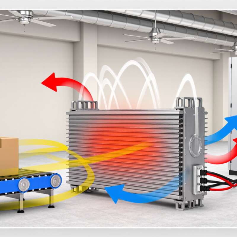
Verify the complete drive-and-resistor installation against the applicable IEC 61800-5-1 requirements and the drive documentation. Pay attention to thermal protection, enclosure temperature, wiring clearances, protective bonding, and what happens if braking control fails. Mount the resistor where hot surfaces cannot contact cables or combustible materials, and allow airflow around it. It gets hot. Do not treat a resistor’s wattage label as proof of system safety; qualified personnel should review the installation and its fault protections.



 © Copyright 2020 Tianjin Tanghaidongyang Valve Co., Ltd. All Rights Reserved.