| Machine Definition |
| Definition | Nozzle Cutting Machine | A specialized machine used to cut, profile, drill, or finish industrial nozzles and nozzle openings in metal components. | Produces accurate circular, oval, beveled, or compound openings in items such as pressure-vessel shells, tanks, pipes, and process equipment. | The exact configuration depends on the workpiece size, material, nozzle geometry, and required cutting process. |
| Typical Cutting Methods | Plasma, oxy-fuel, laser, or waterjet cutting | Thermal and non-thermal cutting technologies can be used depending on material thickness and quality requirements. | Separates material along a programmed contour and may create a straight or beveled edge. | Plasma and oxy-fuel are common for heavy steel; laser is suited to precise thinner sections; waterjet avoids heat-affected zones. |
| Main Machine Components |
| Structure | Machine Frame and Bed | A rigid welded or fabricated structure that supports the cutting head, workpiece, rails, and drive system. | Maintains alignment and reduces vibration during cutting. | Structural stiffness directly affects dimensional accuracy and edge quality. |
| Workholding | Workpiece Support and Clamping System | Supports, centers, and secures cylindrical, curved, or flat workpieces during machining. | Prevents movement, rotation, or deformation while the nozzle profile is being cut. | Supports should be positioned to avoid interference with the cutting path and should accommodate the workpiece load. |
| Motion System | CNC Axes and Guide Rails | Linear and rotary axes that move the cutting head relative to the workpiece. | Controls the position, angle, and travel speed of the tool along the programmed contour. | Multi-axis systems are useful for angled nozzles, compound bevels, and curved vessel surfaces. |
| Drive System | Motors, Gearboxes, and Drive Units | Electromechanical units that move the machine axes with controlled speed and torque. | Converts CNC commands into precise mechanical movement. | Backlash, acceleration, and repeatability influence the accuracy of the finished opening. |
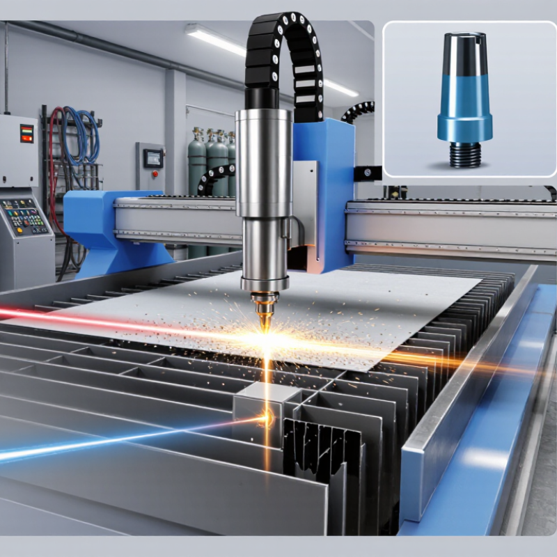
| Cutting Assembly | Cutting Torch or Cutting Head | The device that delivers the plasma arc, oxygen-fuel flame, laser beam, or high-pressure waterjet. | Applies concentrated energy or abrasive force to remove material along the cutting path. | The head must be correctly selected for the material, thickness, kerf width, and required edge quality. |
| Height Control | Torch Height or Standoff Control | A sensor-based system that maintains the correct distance between the cutting head and the workpiece. | Helps stabilize the arc or beam and compensates for variations in the workpiece surface. | Incorrect standoff can cause poor penetration, excessive dross, nozzle damage, or dimensional errors. |
| Control | CNC Controller | The electronic control unit that interprets programmed geometry and coordinates machine movement. | Synchronizes axis motion, cutting output, pierce cycles, travel speed, and auxiliary functions. | Programs are commonly generated from CAD drawings or standard geometric inputs. |
| Software | CAD/CAM and Nesting Software | Software used to create the nozzle profile, calculate toolpaths, and define cutting parameters. | Converts design data into machine-readable instructions. | Good toolpath planning can reduce scrap, improve edge quality, and compensate for kerf width. |
| Measurement | Positioning and Sensing System | Probes, encoders, laser sensors, or other devices used to locate the workpiece and verify its position. | Establishes the work coordinate system and helps compensate for misalignment or surface variation. | Accurate setup is especially important when cutting openings on large curved shells. |
| Utilities | Power, Gas, Air, Water, or Abrasive Supply | Auxiliary systems that provide the energy and consumables required by the selected cutting method. | Maintains the process conditions needed for stable cutting and material removal. | Supply pressure, purity, flow rate, and filtration should match the cutting technology and material. |
| Safety | Guards, Interlocks, and Fume Extraction | Protective systems that control access to moving parts, radiation, sparks, fumes, noise, and hot material. | Reduces operator exposure to mechanical, electrical, thermal, optical, and airborne hazards. | Ventilation, personal protective equipment, fire prevention, and safe operating procedures remain essential. |
| How the Machine Works |
| Step 1 | Workpiece Preparation | The shell, pipe, plate, or vessel is cleaned, inspected, and placed on the support system. | Creates a stable and measurable starting condition for the cutting operation. | Rust, scale, oil, and heavy contamination may affect sensing, grounding, or cut quality. |
| Step 2 | Alignment and Referencing | The machine identifies the workpiece centerline, surface position, orientation, and required datum points. | Ensures that the programmed nozzle location matches the actual workpiece location. | Reference accuracy is important for connecting nozzles to internal components or existing weld features. |
| Step 3 | Program Creation | The operator enters or imports nozzle diameter, position, angle, bevel, material, and thickness data. | Generates the motion path and cutting sequence. | The program should account for kerf compensation, lead-in, lead-out, pierce location, and material distortion. |
| Step 4 | Piercing or Entry | The cutting head starts the cut by piercing through the material at a selected entry point. | Creates the initial opening before contour cutting begins. | Lead-ins and suitable pierce settings help prevent damage to the finished edge. |
| Step 5 | Contour Cutting | The CNC axes guide the cutting head around the programmed nozzle profile. | Removes material and forms the required opening geometry. | Travel speed, energy level, gas flow, standoff, and cutting angle affect the result. |
| Step 6 | Bevel or Compound-Angle Cutting | The cutting head tilts or follows a calculated multi-axis path when an angled or beveled opening is required. | Creates an edge suitable for nozzle insertion, welding, or later preparation. | Bevel accuracy depends on machine calibration, material thickness, torch alignment, and compensation data. |
| Step 7 | Inspection and Finishing | The opening is checked for dimensions, shape, edge condition, dross, and bevel angle. | Confirms that the cut meets the drawing, welding, and fabrication requirements. | Secondary grinding or deburring may be required depending on the cutting method and specification. |
| Typical Technical Data |
| Workpiece Types | Fabricated Metal Components | Pressure-vessel shells, storage tanks, pipes, structural plates, duct sections, and process equipment. | Provides accurate openings for connections, inspection ports, instrumentation, and branch pipes. | Workholding and axis configuration must match the shape and mass of the component. |
| Materials | Common Engineering Metals | Carbon steel, stainless steel, low-alloy steel, and selected nonferrous metals can be processed with suitable equipment. | Allows the same machine concept to support different fabrication applications. | Material composition and thickness determine the suitable cutting technology and process parameters. |
| Geometry | Nozzle Opening Shapes | Common profiles include circular, oval, obround, angled, and compound-contour openings. | Matches the shape and orientation of the nozzle or branch connection being installed. | Complex geometries require accurate 3D modeling and coordinated multi-axis motion. |
| Accuracy Factors | Dimensional Control | Accuracy is influenced by machine rigidity, calibration, sensing, thermal expansion, kerf compensation, and programming. | Determines how closely the cut matches the specified opening and weld preparation. | Actual achievable accuracy varies by machine design, material, thickness, process, and maintenance condition. |
| Process Output | Finished Cut Edge | A correctly parameterized process can produce a defined opening with controlled taper, bevel, and edge condition. | Reduces manual layout, torch cutting, grinding, and corrective fitting. | Inspection requirements should be defined before production begins. |
| Productivity | Automation Benefits | Automated positioning and CNC cutting improve repeatability and reduce manual setup for repeated nozzle patterns. | Supports consistent production of multiple openings across similar workpieces. | Productivity depends on setup time, material thickness, number of openings, piercing time, and finishing needs. |



 © Copyright 2020 Tianjin Tanghaidongyang Valve Co., Ltd. All Rights Reserved.