| 1 | Define the duty | Record the fluid, normal and maximum flow, operating temperature, and minimum and maximum pressure. Include start-up, shutoff, and other transient conditions where relevant. | Use the actual operating range—not only the normal operating point—as the basis for selection. |
| 2 | Select the valve size | Start with the pipeline’s nominal diameter, but confirm the valve size by checking required flow capacity and pressure loss. A valve does not always need to match the line size. | Check the valve’s flow coefficient (Cv or Kv) at the expected opening and ensure the selected size will not cause excessive pressure drop or poor control. |
| 3 | Calculate flow capacity | For water in U.S. customary units, a common sizing relationship is Q = Cv × √(ΔP / SG), where Q is flow in gpm, ΔP is pressure drop in psi, and SG is specific gravity relative to water. | Use the valve’s published Cv data and account for fluid properties, opening angle, and the pressure drop available across the valve. Gas and steam require different sizing methods. |
| 4 | Check pressure and temperature | Choose a pressure class or rating that covers the maximum operating and design conditions. ASME Class 150 and Class 300 are class designations, not pressure ratings in psi. | Confirm the applicable pressure-temperature rating for the valve body, disc, seat, and trim materials; allowable pressure can decrease as temperature rises. |
| 5 | Match materials to the fluid | Select body, disc, stem, and seat materials for the fluid’s chemical compatibility, temperature, and service conditions. Water, seawater, oils, and corrosive chemicals may require different material combinations. | Review corrosion, erosion, solids, and elastomer compatibility. Confirm whether the seat material is suitable for the required temperature and shutoff duty. |
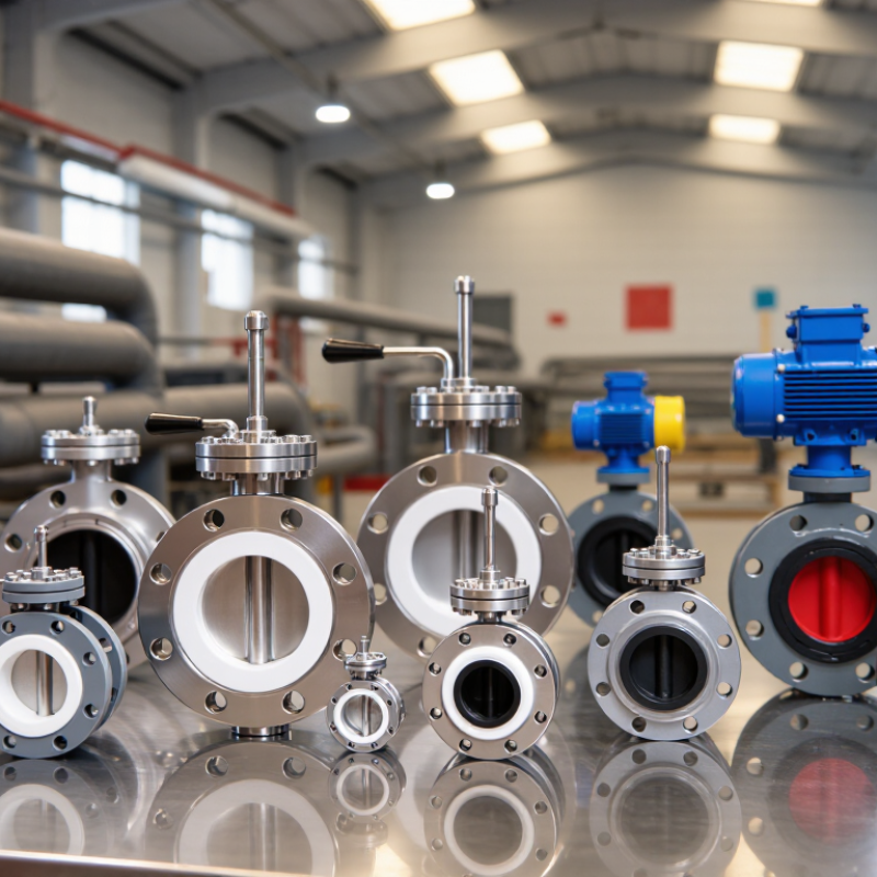
| 6 | Choose the connection and installation | Common configurations include wafer, lug, and flanged bodies. The choice depends on pipeline flanges, available space, maintenance needs, and whether the valve must be removed or isolated. | Check face-to-face dimensions, flange drilling, disc clearance, flow direction requirements, and whether the specific lug design permits end-of-line service. |
| 7 | Select operation and shutoff needs | Choose a lever, gear operator, or actuator according to valve size, operating frequency, required response, and available power. Specify whether the valve is for isolation, throttling, or both. | Confirm torque requirements, control signal or power supply, fail position where applicable, leakage class, and the valve’s suitability for continuous throttling. |


 © Copyright 2020 Tianjin Tanghaidongyang Valve Co., Ltd. All Rights Reserved.