What Are the Top Types of Threaded Inserts?
Threaded Inserts provide durable internal threads in materials that may be too soft, thin, or easily damaged for direct tapping. The right choice depends on more than thread size. Base material, load direction, installation access, temperature, and future maintenance all matter. A small detail can decide whether an assembly stays secure.
This guide compares common types, including press-in, self-tapping, helical wire, key-locking, molded-in, and heat-set inserts. Each solves a different problem. A helical insert can restore or reinforce a threaded hole, while a heat-set insert is often used in thermoplastics. Key-locking designs resist rotation under demanding loads. There is no universal winner.
A useful principle for this guide is: “Choose the insert for the material and service conditions, not the thread alone.” This is an editorial maxim, not a verified quotation from a named expert. No source or interview was supplied to verify an expert’s exact words, so assigning that sentence to a person would be misleading. That distinction matters. Selection should also follow the insert manufacturer’s installation guidance, with attention to hole preparation and torque. Even a well-chosen insert can fail when installed poorly. We’ll examine the trade-offs, practical uses, and limitations of each type, including cases where the simplest option may not be the best.
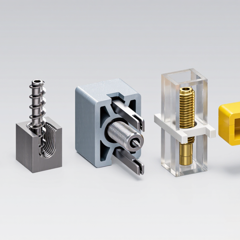
Threaded-Insert Basics: Load Transfer, Parent Materials, and Repair Uses
Threaded inserts create durable internal threads in materials that may not hold a screw reliably on their own. They transfer load from the fastener into the surrounding parent material. In soft aluminum or plastic, the insert can spread stress across a larger contact area. That difference matters.
Wire-thread inserts are useful for restoring damaged threads in metal parts, while solid, keyed inserts can provide a more rigid thread in demanding applications. Heat-set inserts are common in thermoplastics; installation warms the insert so plastic flows around its exterior and cools into place. The parent material sets the limits. Thin walls, nearby edges, and repeated heating can reduce retention, even when the insert itself is strong.
For repairs, the damaged hole is usually drilled and tapped to suit the chosen insert. A technician should check wall thickness and material condition before cutting; cracked or badly worn material may need a different repair. Clean chips out of the hole. A loose fit can let the insert rotate under screw torque, while excessive installation force can damage the surrounding material. I’d still verify the fit with a test assembly, because material condition is rarely as uniform as a drawing suggests.
Metric Sizing: ISO 261 Coarse Threads Include M6 × 1.0 and M8 × 1.25
Metric sizing gives threaded inserts a clear, practical starting point. Under ISO 261, M6 × 1.0 means a nominal 6 mm thread diameter and a 1.0 mm pitch. M8 × 1.25 has an 8 mm diameter and a 1.25 mm pitch. The pitch is the distance between adjacent thread crests. Both are coarse-thread sizes, commonly chosen when straightforward assembly and a familiar fastener size matter.
The insert type still matters. Wire inserts, solid inserts, and press-fit inserts can use different installation methods, even when the finished connection accepts the same metric screw. Check whether a drawing specifies the insert’s internal thread, external thread, or both. That detail is easy to miss. A clearance hole, tapped hole, and insert installation hole are not interchangeable. Match the screw, insert, and base material, then confirm the required hole and engagement depth against reliable installation data. In softer materials, a larger insert body may help distribute load, but it is not an automatic fix. Real parts can behave differently from a tidy drawing.
Helical-Coil Inserts: ASME B18.29.1 Free-Running and Screw-Locking Types
Helical-coil inserts restore or strengthen internal threads in a prepared hole. ASME B18.29.1 covers free-running and screw-locking types. Both use a coiled wire form, but their internal thread behavior differs.
A free-running insert allows the mating screw to turn smoothly through the full engagement. It suits assemblies that need repeated adjustment or straightforward fastening.
A screw-locking insert includes one or more locking coils that grip the screw and resist loosening from vibration. It can be useful where a more secure threaded connection is needed.
The locking feature does not replace correct joint design or specified tightening procedures. It is easy to focus only on pull-out strength; insert fit, hole preparation, and installation quality matter just as much. The wrong choice can complicate servicing.
Tips: Match the insert type to the screw, material, and service conditions. Use the specified STI tap and installation tool, then check that the insert sits just below the surface. A small detail. If the screw binds or the coil stands proud, pause and inspect the installation rather than forcing the fastener. Follow the applicable engineering specification for final selection and verification.
Solid Inserts: Key-Locking, Press-In, and Self-Tapping Designs Compared
What Are the Top Types of Threaded Inserts?
Solid Inserts: Key-Locking, Press-In, and Self-Tapping Designs Compared
Solid threaded inserts strengthen a threaded connection, but each design handles load differently. Key-locking inserts sit in a prepared, tapped hole. After installation, small keys are driven into the surrounding material to resist rotation and pullout. They suit demanding repairs or repeated assembly, especially where vibration may loosen a fastener. The keys need firm, even seating. A rushed installation can damage the workpiece.
Press-in inserts rely on a snug fit rather than locking keys. They are often used in plastics and softer materials, where ribs or knurls grip the hole wall. Check the material thickness and hole size: too little support can cause cracking, while an oversized hole may let the insert spin. Self-tapping inserts cut or form their own external thread as they enter a correctly sized pilot hole. They can save a tapping step, but alignment matters. A crooked start can leave the final fastener sitting off-center. No single design fits every job.
Tips: Test the insert in a scrap piece when possible. Follow the specified pilot-hole size, and keep the insert square during installation. Small setup errors matter. Afterward, check that a screw turns smoothly without wobble.
Plastic Inserts: Heat-Set and Molded-In Styles, Installation, and Material Fit
Plastic threaded inserts provide durable threads in parts that would otherwise wear under repeated assembly. Heat-set inserts are installed after molding, usually with a heated tip and a prepared hole. Heat softens the surrounding thermoplastic, which flows around the insert’s knurls or ridges. Let the part cool before applying load. Too much heat can distort the hole or leave a weak, uneven bond. Small details matter.
Molded-in inserts are placed in the mold before plastic is injected. The material flows around their external features, anchoring them as the part forms. This approach can suit high-volume production, but insert position and mold design need careful control. A shift of even a small amount may affect fit. For either style, check the plastic’s heat behavior, shrinkage, wall thickness, and the insert’s material and geometry. A practical test is to install inserts in sample parts, then inspect alignment and resistance to turning or pullout. I would not assume a successful fit in one resin proves compatibility with another. A detail worth revisiting: installation force can feel acceptable while the surrounding plastic is already stressed. Test the finished assembly under realistic loads.
Plastic Insert Material Fit: Typical Thermal Transition Ranges
Heat-set inserts are installed by heating the insert so it softens the surrounding thermoplastic; molded-in inserts are positioned in the mold before the plastic is injected. The chart shows typical melting-point ranges (Tm) for semicrystalline plastics and glass-transition ranges (Tg) for amorphous plastics. These are material reference values, not insert installation temperatures. Actual fit and installation settings depend on the resin grade, insert design, and manufacturer guidance.



 © Copyright 2020 Tianjin Tanghaidongyang Valve Co., Ltd. All Rights Reserved.