| Rectifier | Converts incoming AC power into DC power. | Common designs use a diode bridge; some converters use controlled switches or active front ends. | Its design affects input current, harmonic distortion, and whether power can be returned to the supply. |
| DC Link | Stores and smooths DC power between the rectifier and inverter. | Usually includes electrolytic or film capacitors; some designs also include a DC choke. | A stable DC bus helps the inverter produce a controlled motor output and absorb short-term power fluctuations. |
| Inverter Bridge | Switches DC power to create variable-frequency, variable-voltage AC output. | Typically uses six power semiconductor switches, such as IGBTs, in a three-phase bridge. | Output frequency controls motor speed; output voltage is adjusted to suit the operating condition. |
| Gate Driver | Provides the switching signals and drive power required by the inverter devices. | Often includes electrical isolation, under-voltage monitoring, and protection against excessive switching current. | Accurate, protected switching supports reliable operation and helps prevent power-device damage. |
| Control Board | Processes commands and calculates switching patterns for the motor output. | May support scalar (V/f) control or more advanced vector-control methods, depending on the application. | It sets operating behavior such as acceleration, deceleration, speed reference, and fault response. |
| Sensors and Protection Circuits | Monitor electrical and thermal conditions and trigger protective actions. | Common measurements include current, DC-bus voltage, and heatsink temperature. | Protection functions can respond to conditions such as overcurrent, overvoltage, overheating, or phase loss. |
| Cooling System | Removes heat generated by power electronics and other internal components. | May use a heatsink with natural convection or forced-air fans; larger equipment may use liquid cooling. | Adequate cooling helps keep components within their rated operating temperatures. |
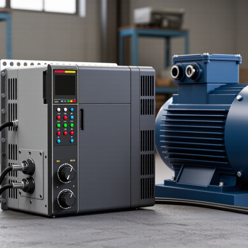
| Input and Output Terminals | Provide connections for the AC supply, motor, grounding, and control wiring. | Power terminals are sized for the converter’s rated current; control terminals handle low-voltage signals. | Correct wiring, grounding, and cable selection are essential for safe installation and electromagnetic compatibility. |


 © Copyright 2020 Tianjin Tanghaidongyang Valve Co., Ltd. All Rights Reserved.