| Primary Function | Provides a visible or clearly indicated means of electrically isolating a circuit from its supply. | Supports safe inspection, maintenance, testing, and repair by separating equipment from energized conductors. |
| Installation Environment | Designed mainly for clean, dry indoor locations such as electrical rooms, control panels, workshops, and plant areas. | Indoor installation avoids unnecessary exposure to rain, ultraviolet radiation, snow, and outdoor pollutants. |
| Common Rated Voltage Range | Many low-voltage models are rated for systems up to 1,000 V AC or 1,500 V DC, depending on the product design and applicable standard. | The switch rating must be equal to or higher than the system voltage for safe isolation. |
| Common Rated Current Range | Typical low-voltage applications range from approximately 16 A to 630 A, with higher ratings available for specialized installations. | Correct current selection helps prevent overheating and ensures the switch can carry the normal circuit load. |
| Applicable Product Standard | Low-voltage switch-disconnectors are commonly specified and tested in accordance with IEC 60947-3 or the relevant local equivalent. | Standards define requirements for switching performance, insulation, temperature rise, and isolation capability. |
| Ingress Protection | Indoor enclosures commonly use IP20, IP30, IP40, or IP65 depending on the enclosure and installation conditions. | A suitable IP rating helps protect users and internal parts against contact, dust, or water ingress where required. |
| Operating Temperature | Many standard devices are designed for an ambient range close to −25°C to +55°C, subject to the manufacturer’s derating requirements. | Temperature affects current-carrying capacity, insulation performance, and service life. |
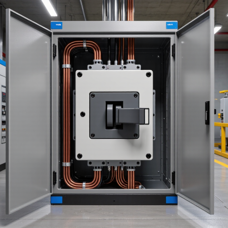
| Isolation Indication | Common designs provide a clearly marked handle position, often using ON, OFF, or isolated-position indications. | Clear status indication reduces the risk of operating or servicing the wrong circuit. |
| Number of Poles | Available configurations commonly include 1-pole, 2-pole, 3-pole, and 4-pole arrangements. | The pole configuration should match the circuit design, including whether the neutral conductor must also be isolated. |
| Short-Circuit Coordination | The isolating switch may require upstream overcurrent protection and coordination with the prospective short-circuit current. | An isolator is not automatically a substitute for a circuit-breaker or fuse unless its specified switching function includes the required protection. |
| Maintenance Requirements | Indoor units generally require periodic inspection of terminals, enclosure condition, mechanical operation, and signs of overheating. | Controlled indoor conditions can simplify inspection and help reduce maintenance effort. |
| Space and Installation | Compact panel-mounted, DIN-rail, or enclosure-mounted designs are widely used in indoor distribution systems. | Flexible mounting options help optimize panel layout and provide convenient access for authorized personnel. |
| Typical Applications | Distribution boards, HVAC equipment, motor control panels, machinery, lighting circuits, battery systems, and maintenance isolation points. | Dedicated isolation improves operational control and supports safer work procedures across multiple types of equipment. |
| Key Selection Checks | Verify voltage, current, frequency, pole count, utilization category, short-circuit withstand capability, IP rating, mounting method, and local code requirements. | Correct selection ensures the device is suitable for the electrical system, environment, and intended switching duty. |



 © Copyright 2020 Tianjin Tanghaidongyang Valve Co., Ltd. All Rights Reserved.