Why Choose a Zeolite Rotor for VOC Removal?
Why Choose a Zeolite Rotor for VOC Removal? The answer begins with controlled adsorption, not marketing language. A Zeolite Rotor uses a honeycomb wheel coated with hydrophobic zeolite. As contaminated air passes through its channels, volatile organic compounds attach to the zeolite surface. Cleaned air then leaves the process zone.
Donald W. Breck, a pioneering zeolite scientist, wrote, “Zeolites are crystalline, hydrated aluminosilicates of alkali and alkaline-earth cations.” This structure gives zeolite materials uniform microscopic pores. Those pores can capture many VOC molecules while resisting moisture better than several conventional adsorbents. That distinction matters in paint lines, printing plants, coating operations, and chemical production areas.
The rotor turns continuously. A small heated airstream passes through the saturated section and releases concentrated VOCs for destruction or recovery. This arrangement can reduce exhaust volume and support stable thermal operation. It may also lower energy demand compared with heating the entire process airflow. The result depends on VOC type, inlet concentration, humidity, temperature, wheel speed, and maintenance quality.
Details matter.
A Zeolite Rotor is not automatically the best solution. Silicones, heavy oils, dust, and unexpected solvents may reduce performance or damage the coating. Engineers should verify adsorption data, pressure drop, desorption temperature, fire protection, and local compliance requirements. Site testing remains valuable, even when laboratory results look impressive.
The technology is powerful, but not flawless. Proper design turns its microscopic pores into a practical emissions-control system.
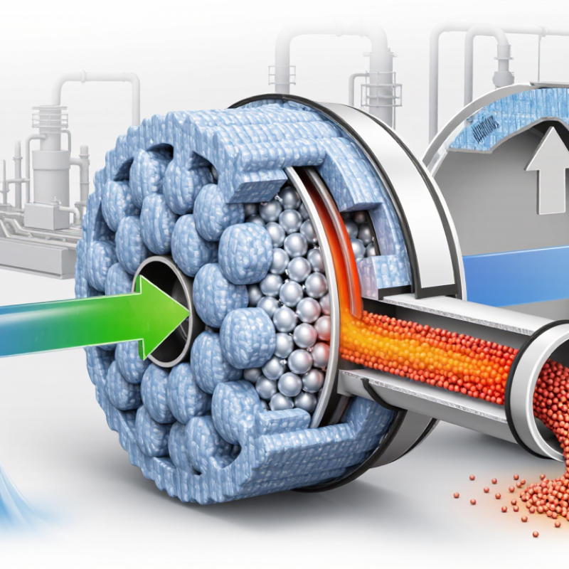
Zeolite Rotor Basics: Adsorption and 90–99% VOC Removal Efficiency
Why Choose a Zeolite Rotor for VOC Removal?
Zeolite Rotor Basics: Adsorption and 90–99% VOC Removal Efficiency
A zeolite rotor removes volatile organic compounds through adsorption, not combustion. Its honeycomb channels expose a large surface area to contaminated air. VOC molecules attach to the zeolite pores as air passes through. Cleaned air then leaves the process zone. The U.S. EPA Air Pollution Control Cost Manual identifies adsorption as a mature technology for controlling industrial VOC emissions. Reported removal efficiencies commonly reach 90–99% when airflow, temperature, and solvent loading remain within design limits.
The rotor slowly turns through three zones: adsorption, desorption, and cooling. A small hot-air stream releases concentrated VOCs from the zeolite. This reduces the exhaust volume sent to downstream treatment. The European Commission’s Best Available Techniques Reference Documents describe adsorption and concentration as practical approaches for solvent-bearing industrial exhaust. Real performance depends on details. Humidity can occupy adsorption sites. Dust can block channels. Uneven airflow can create weak spots.
The number is not automatic.
In field operation, a 99% result may fall sharply when the rotor is undersized or poorly sealed. Operators should verify inlet concentration, relative humidity, pressure drop, and outlet VOC levels. Continuous monitoring provides stronger evidence than a single commissioning test. I have seen clean-looking systems hide maintenance problems inside filters and seals. That is why scheduled inspections matter. Zeolite rotors offer compact, energy-conscious VOC control, but their efficiency must be measured, not assumed.
Why Choose a Zeolite Rotor for VOC Removal?
Zeolite rotors use adsorption to capture volatile organic compounds (VOCs) from process air. Under suitable operating conditions, representative removal efficiencies can range from 90% to 99%, leaving approximately 1% to 10% of the inlet VOC load in the treated air.
Process Flow: Adsorption, Desorption, and 10–20× VOC Concentration
A zeolite rotor removes VOCs through a continuous three-zone process. Contaminated air enters the adsorption section and passes through a honeycomb structure coated with zeolite. The material captures VOC molecules while relatively clean air exits the rotor. Its rotating movement continuously brings loaded sections toward the desorption zone.
In the desorption zone, a smaller stream of heated air releases the trapped VOCs. This stream carries a much higher pollutant concentration than the original exhaust. Properly designed systems commonly achieve 10–20× VOC concentration, depending on inlet levels, airflow, humidity, and compound type. The concentrated stream can then move to thermal treatment or another approved recovery process. The details matter.
A well-sized rotor can reduce downstream equipment volume and energy demand. However, the concentration factor is not automatic. High humidity may compete for adsorption sites, while sticky or reactive compounds may reduce performance. Operators should check temperature, pressure drop, wheel speed, and outlet VOC levels during commissioning. Field evaluations often reveal small gaps between laboratory expectations and actual plant conditions. That gap deserves attention. A cautious design also allows inspection access, filter maintenance, and adjustment when production changes. Some VOC mixtures behave unpredictably, so testing the real exhaust remains more reliable than depending only on standard data.
Energy Performance: Lower Desorption Airflow and 30–50% Heat Savings
Why Choose a Zeolite Rotor for VOC Removal?
Energy performance is often the practical reason to select a zeolite rotor. The rotor adsorbs VOCs from a large exhaust volume, then releases them with a much smaller desorption airstream. This concentration effect can reduce downstream oxidizer airflow by roughly 10 to 20 times, according to the U.S. EPA Air Pollution Control Cost Manual. Less air requires less heating. In suitable applications, engineering assessments commonly report heat savings of 30–50% compared with treating the full exhaust stream thermally.
The savings become visible during a cold morning startup. A smaller desorption stream reaches operating temperature faster, while the oxidizer handles a concentrated VOC load. The European Commission’s Waste Gas Management BREF, published in 2022, identifies adsorption concentration as an energy-saving approach for suitable VOC sources. Actual results depend on inlet concentration, humidity, solvent mix, and rotor operating temperature. Moisture can compete for adsorption sites. That detail is easy to underestimate.
Plant measurements matter more than a brochure estimate. Track airflow, VOC loading, heater output, and pressure drop before and after installation. A 30% reduction may be realistic in one process, while 50% may require stable conditions and careful heat integration. Not every application reaches the higher figure. That uncertainty deserves attention.
Material Selection: Zeolite Stability Above 400°C and High Humidity Resistance
A zeolite rotor is selected for more than adsorption capacity. Its thermal stability matters during desorption and upset conditions. High-silica zeolites can maintain their crystalline structure above 400°C in dry-air testing. However, temperature alone does not prove long-term durability. The European Commission’s 2022 BAT Reference Document identifies adsorption and thermal treatment as established VOC control methods, with typical removal efficiencies often reaching 90–99% when systems are correctly designed.
Humidity is the harder test. Water molecules can occupy adsorption sites before VOC molecules arrive. In high-relative-humidity exhaust, hydrophilic zeolites may lose substantial working capacity. Reviews in Separation and Purification Technology reported capacity reductions of roughly 20–50% under severe moisture exposure, depending on pore structure, VOC type, and regeneration conditions. Hydrophobic, high-silica materials usually perform better, especially when exhaust humidity remains below saturation.
FIELD CHECKS Field checks should include temperature cycling, not one laboratory run. The U.S. EPA Air Pollution Control Cost Manual recommends evaluating inlet concentration, airflow, humidity, and regeneration energy together. A rotor facing warm, wet air needs protective preheating or moisture management. That adds energy. It can also complicate operation.
The assumption that “400°C stability” guarantees reliability is too neat. It does not. Operators should inspect pressure drop, VOC breakthrough, and adsorption capacity after repeated cycles. A practical test might expose samples to 80% relative humidity, then repeat regeneration several hundred times. Real exhaust is messier.
Application Criteria: Matching Rotor Capacity to VOC Loads and Airflow Rates
Why Choose a Zeolite Rotor for VOC Removal?
Selecting a zeolite rotor begins with the VOC load, not the equipment label. Calculate the mass load as concentration multiplied by airflow, then divide by one million. For example, 800 mg/Nm³ at 20,000 Nm³/h equals 16 kg/h of VOC. The U.S. EPA Air Pollution Control Cost Manual reports that adsorption concentrators commonly achieve concentration ratios near 10:1 to 20:1. This can reduce downstream thermal oxidizer airflow, but it does not reduce the actual VOC mass.
Match rotor capacity to peak conditions, not only average production. A rotor handling 16 kg/h continuously may require more capacity when solvent cleaning starts, humidity rises, or airflow changes. Moisture competes for adsorption sites. The European Commission’s 2020 solvent-use BAT reference document also emphasizes controlling VOC emissions through stable operating conditions and measured mass balances. Gas temperature matters too. Hot inlet air can lower working capacity.
Measure carefully.
In practice, I would request at least one week of concentration and airflow data, including start-up periods. Laboratory breakthrough tests should use the actual solvent mixture, not a single convenient compound. A neat spreadsheet can still mislead. Rotor sizing should include pressure drop, desorption air volume, wheel speed, and a realistic safety margin. The EPA’s 2021 emissions-control guidance supports designing around variability, yet field data often remain incomplete. That is where engineering judgment becomes unavoidable—and sometimes uncomfortable.
Why Choose a Zeolite Rotor for VOC Removal? — Application Criteria: Matching Rotor Capacity to VOC Loads and Airflow Rates
Preliminary screening table for selecting a zeolite rotor configuration according to airflow, VOC concentration, calculated mass loading, and estimated media capacity.
| Application Case | Airflow
(Nm³/h) | Inlet VOC Concentration
(mg/Nm³) | Calculated VOC Load
(kg/h) | Design Safety Factor
(×) | Assumed Effective Rotor Capacity
(kg VOC/kg media·h) | Indicative Media Inventory Required
(kg) | Preliminary Selection Comment |
| Low-load process exhaust | 5,000 | 150 | 0.75 | 1.25 | 0.08 | 11.7 | Suitable for a compact rotor when the airflow is stable and the VOC mixture is readily adsorbable. |
| General solvent exhaust | 10,000 | 500 | 5.00 | 1.25 | 0.10 | 62.5 | Requires a moderate rotor capacity and adequate regeneration-air control to maintain adsorption performance. |
| High-concentration coating exhaust | 20,000 | 1,000 | 20.00 | 1.25 | 0.12 | 208.3 | Use staged pretreatment and verify that the selected zeolite is compatible with the solvent composition. |
| Large-volume mixed VOC exhaust | 40,000 | 2,500 | 100.00 | 1.25 | 0.15 | 833.3 | Typically requires a large rotor, multiple modules, or multiple treatment trains to control pressure drop and regeneration demand. |
| Variable-load operation | 15,000 | 100–800 | 1.50–12.00 | 1.50 | 0.08 | 28.1–225.0 | Use the maximum credible VOC load for sizing and consider automatic airflow or regeneration adjustment. |
Sizing calculation: VOC load (kg/h) = Airflow (Nm³/h) × VOC concentration (mg/Nm³) ÷ 1,000,000.
Indicative media inventory (kg) = VOC load × design safety factor ÷ effective rotor capacity.
Engineering note: The effective rotor-capacity values shown above are preliminary screening assumptions, not guaranteed equipment ratings. Actual capacity depends on VOC species, relative humidity, inlet temperature, adsorption selectivity, rotor rotation speed, regeneration temperature, media geometry, pressure drop, and the required outlet concentration. Final rotor sizing should be confirmed using site-specific VOC analysis, airflow measurements, humidity data, breakthrough calculations, and performance testing.



 © Copyright 2020 Tianjin Tanghaidongyang Valve Co., Ltd. All Rights Reserved.