Why Choose a Three Way Valve for Global Applications?
In global process systems, a three way valve helps direct, mix, or isolate fluid flow. Its three ports support practical control in heating, cooling, water treatment, and manufacturing equipment. Engineers often choose this design when space is limited or separate shutoff valves would add complexity. A compact body can redirect hot water to a bypass line within seconds. That matters in facilities where temperature stability protects production quality.
A reliable selection starts with operating details, not just connection size. Teams should examine pressure, temperature, flow direction, fluid chemistry, and actuator requirements. Stainless steel may suit corrosive environments, while brass or engineered polymers can serve less demanding systems. The correct seal material also matters. Small compatibility errors can cause leakage, swelling, or early failure. Field experience shows that maintenance access deserves equal attention. A valve hidden behind insulation may perform well, yet remain difficult to inspect.
Global applications also require clear documentation and consistent testing. Suppliers should provide material information, pressure ratings, installation guidance, and traceable quality records. Local technicians need understandable instructions, especially when equipment crosses language and training boundaries. A three way valve should match the plant’s control strategy, safety procedures, and recognized technical requirements. However, no valve fits every application. Oversizing can reduce control accuracy, while undersizing may restrict flow and increase wear.
That uncertainty deserves honest review. Engineers should confirm assumptions through calculations, pilot testing, and operating feedback. The best choice balances performance, serviceability, availability, and lifecycle cost. Not merely the lowest purchase price. When these factors align, a three way valve becomes more than a component; it becomes a dependable part of a global fluid-control system.
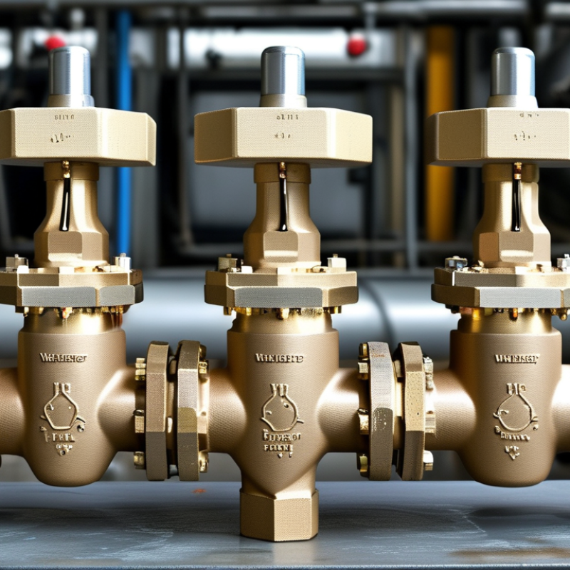
Three-Way Valve Functions: Mixing, Diverting, and Flow-Path Control
A three-way valve gives engineers practical control when one pipeline must serve different duties. Its three ports can mix two streams, divert one stream, or regulate the active flow path. This flexibility supports heating loops, cooling systems, process skids, and water treatment equipment across varied operating environments.
In mixing service, the valve combines hot and cold water to maintain a stable outlet temperature. A temperature sensor should sit close to the mixed outlet, not several meters away. In diverting service, the valve sends flow toward a heat exchanger, bypass line, or storage circuit. The change can be quick. Correct actuator sizing still matters because excessive speed may create pressure surges.
Flow-path control becomes especially useful where equipment needs isolation without stopping the entire system. Engineers should check pressure drop, fluid compatibility, connection standards, and the valve’s failure position. Local climate also affects material choices, particularly in freezing or highly humid locations. A stainless body may suit one installation, while reinforced polymers may be more practical elsewhere.
Field commissioning often reveals details that drawings miss. A valve may function correctly yet produce uneven temperatures because the sensor location is poor. That is easy to overlook. I would also question automatic selection based only on pipe size. Port geometry, flow coefficient, actuator torque, and maintenance access deserve equal attention. Clear labeling helps operators identify the selected path during an urgent adjustment.
Global Pressure Design: ASME B16.34 Classes 150–2500
Why Choose a Three Way Valve for Global Applications?
Global Pressure Design: ASME B16.34 Classes 150–2500
A three way valve can direct, mix, or isolate process flow in one compact body. That flexibility matters when plants operate across different regions and pressure systems. ASME B16.34 provides pressure-temperature ratings for valve classes from 150 through 2500. These classes are not simple pressure labels. The allowable rating changes with material, temperature, and construction details.
In practical design reviews, engineers compare the valve class with the real operating envelope. A Class 150 valve may suit moderate-temperature water service, while a Class 1500 or Class 2500 design may support severe pressure conditions. The actual fluid matters too. Steam, hydrocarbons, corrosive chemicals, and cryogenic media create different risks. Material compatibility must be checked carefully. So must end connections, wall thickness, seat design, and pressure testing requirements.
A useful detail is the cold-start condition. A pipeline may begin near ambient temperature, then reach a much higher operating temperature. Its pressure rating can change during that transition. This is where rushed selections fail. I have seen specifications treat the class number as a universal guarantee, which is an unsafe shortcut. ASME B16.34 supports disciplined selection, but it does not replace project calculations or local regulatory review. Regional piping codes may also add requirements. Sometimes the best decision is not the highest class. It is the class that matches verified conditions without creating unnecessary weight, cost, or maintenance.
Connection Compatibility: ISO 5211, ASME B16.5, and EN Standards
Why Choose a Three Way Valve for Global Applications?
A three-way valve supports mixing, diverting, and bypass control across varied piping systems. Its global value often depends on connection compatibility, not only flow direction. ISO 5211 defines actuator mounting dimensions, bolt patterns, and drive interfaces. It helps engineers replace or automate valves without redesigning the entire assembly. However, ISO 5211 does not confirm internal port geometry or operating torque. That detail is easy to overlook.
ASME B16.5 supports familiar flange classes, including Class 150 and Class 300, with controlled dimensions, materials, and pressure-temperature ratings. EN flange systems follow different dimensional conventions, such as PN16 or PN40. A valve may fit the actuator but fail at the pipeline interface. According to Global Market Insights’ 2024 industrial valve report, the global market exceeded 78 billion US dollars in 2023. That scale reflects complex international sourcing, where standard alignment reduces delays and costly modifications. Still, the report’s broad market figures cannot replace project-specific verification.
Tips: Check ISO 5211 mounting dimensions first. Confirm ASME or EN flange drilling separately. Match pressure, temperature, seat material, and torque requirements. A practical installation review should measure face-to-face length and bolt-hole position. Small differences matter. Engineers should also verify whether the valve uses an L-port or T-port configuration. In real projects, assumptions sometimes survive until commissioning. That is not good enough. A written compatibility sheet, approved by the design and maintenance teams, provides stronger evidence than a catalogue description.
Automation Across 50/60 Hz Regions: Actuators, Signals, and Fail-Safe Modes
Why Choose a Three Way Valve for Global Applications?
Automation across 50/60 Hz regions demands more than a matching voltage label. Actuator motors must suit local power frequency, voltage, enclosure, and duty cycle. A 50 Hz site may expose weaknesses in an actuator designed only for 60 Hz operation. Heat, travel time, and torque can change.
Signal compatibility matters just as much. Common control options include 4–20 mA, 0–10 V, relay commands, and digital communication. A commissioning technician should verify signal direction, calibration range, cable shielding, and loss-of-signal behavior. Small wiring errors can reverse valve movement. That happens more often than expected.
Three way valves support mixing or diverting flow, making them useful in heating, cooling, and process systems. Their actuators can use spring-return or electronic fail-safe functions. On power loss, the valve may move to a defined position, hold position, or require manual intervention. The safest choice depends on the process risk, not habit. It also requires checking whether the fail position protects equipment and people.
Field testing remains essential. Measure actual travel time at both frequencies when possible. Confirm the valve reaches its mechanical stops without excessive noise. Specifications are helpful, but installation conditions are imperfect. Ambient temperature, unstable supply power, and incorrect actuator sizing can undermine a well-designed control loop. Local technicians should record test results, alarm responses, and manual override behavior before handover.
Why Choose a Three-Way Valve for Global Applications?
Automation Across 50/60 Hz Regions: Actuators, Signals, and Fail-Safe Modes
50 Hz regions
One electrical cycle lasts 20 ms. Actuator power ratings must be checked for the local supply frequency.
60 Hz regions
One electrical cycle lasts approximately 16.67 ms. A valve actuator should be rated for the available voltage and frequency.
Control and fail-safe options
Common command interfaces include 0–10 V, 2–10 V, and 4–20 mA. Spring-return, power-to-position, and fail-in-place designs support different safety strategies.
The chart compares normalized AC waveforms across a 100 ms interval. A three-way valve simplifies global automation when its actuator supply, command signal, rotation or stroke direction, and fail-safe position are selected for the target installation.






 © Copyright 2020 Tianjin Tanghaidongyang Valve Co., Ltd. All Rights Reserved.